


PG2T390
Model
AXP392Price
$ 1280
PANGOMICRO SoM Boards Logos2 Series PG2T390H SDI input/output
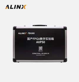
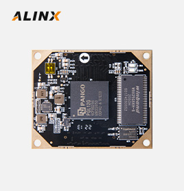
PANGOMICRO SoM Boards Logos Series PGL50H Embedded Teaching Experiment Box Learning
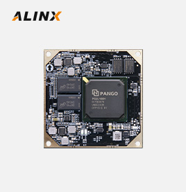
PANGOMICRO SoM Boards Logos Series PGL12G Video Imaging
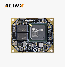
PANGOMICRO SoM Boards Logos2 SeriesPG2L100H Industrial grade domestic FPGA core board for transceivers
PANGOMICRO SoM Boards Logos Series PGL50H Industrial grade domestic DDR3
Meet the requirements of various PCIe high-speed data transmission, video image processing, and industrial control for users

FPGA Board
AN9767 Collection Packag
AN706 Collection Packag
AN9238 Collection Packag
Video Processing Packge
Luxury Package
FPGA Board
●
●
●
●
●
●
USB Downloader
●
●
●
●
●
●
AN9767
●
●
AN706
●
●
AN9238
●
●
AN5642
●
●
4.3-Inch LCD
●
●
Supporting Modules in the Package, Click to Learn More


Learn More about the Core Board, Click to View>>

FPGA Chip
PG2T390HFFBG900
FF
487200
LUT6
243600
DRM(36Kbits)
480
APM
840
GPLL
10
PPLL
10
ADC
1 dedicated analog channel; Reuse 11 analog channels
PCIe Gen3 x8
1
Working Temperature
Industrial grade -40℃-85℃
Speed Grade
-6
DDR4
4 x 2 GB DDR4 ,64bit
QSPI Flash
Crystal Oscillator128Mbit QSPI FLASH, Used for FPGA Configuration File and User Data Storage
Crystal Oscillator
200MHz provides a stable clock source for the system
125MHz provides a stable clock output for the GTX transceiver
HSSTHP
16 channels of HSSTHP, each with 13.125Gb/s max, suitable for fiber optic communication and PCIe data communication
PCIe
PCIe 2.0 x8 interface, used for communicating with PCIe on the computer motherboard, with a single channel communication rate of up to 5Gbps
SFP
4-way high-speed SFP fiber optic communication interface, with each receiving and sending speed up to 10Gb/s
JTAG
10-pin 0.1-inch Standard JTAG Port for Debug and Download
3G-SDI
SDI video input and output interfaces each have 2 channels. Supports HDcctv 1.0, HD-SDI (ST 292) 3G_ SDI (ST-424) and SD_ SDI (ST259) data input and output in different formats.
USB
Used for USB 2.0 High Speed Communication with PC
SD Card Slot
1 Micro SD Card Slot, Support SPI Mode
LED
2 LEDs on the core board and 5 LEDs on the expansion board
key
4 Keys
40-Pin Expansion Ports
Reserve two expansion ports with a spacing of 2.54mm and 40 pins, which can be used to connect various modules externally (such as binocular cameras, TFT LCD screens, high-speed AD modules, etc.). The expansion port includes 1 5V power supply, 2 3.3V power supplies, 3 ground power supplies, and 34 IO ports.
power supply
+12 V DC ,Max. Current 3A
FPGA Board
1
Cooling fan
1
Mini USB Cable
1
USB Downloader Cable
1
12V power supply
1
baffle
1
Size Dimension
Core board 80mmx60mm,expansion board 215mm x 111mm
Number of Layers
16-Layer Core Board PCB, 6-Layer Carrier Board PCB Reserve independent power supply layer and GND layer


Fiber optic communication, PCIe acceleration, video processing, high-speed data transmission
Adopting a mode of adding a core board and an expansion board, it facilitates users' secondary development and utilization of the core board. Rich peripheral interfaces: 1 PCIex8 interface, 4 fiber optic interfaces, 2 SDI output interfaces, 2 SDI input interfaces, 1 UART serial interface, 1 SD card interface, 2 40 pin expansion interfaces, etc. Meet the requirements of users for various high-speed data exchange, data storage, video transmission processing, and industrial control. It provides the possibility for early validation and later application of high-speed data transmission and exchange, data processing
Expansion port connected to binocular camera for fiber optic video transmission


The development board collects video images through a camera and transmits them to another development board through a fiber optic interface. After receiving data through the fiber optic interface, it is displayed on the monitor through the SDI interface

Optical fiber communication Link communication eye diagram with a speed of 10.0Gbps
Intelligent identification, medical security, onboard digital, industrial control, smart grid

The binocular camera module AN5642 collects video and displays it on the display through the SDI interface of the development board, achieving binocular synchronous display.
Display diagram of AN9767/AN706 module on computer

*The signal output from the signal source is connected to the AN9767 module and the waveform signal is displayed through an oscilloscope
*The signal output from the signal source is connected to the AN706 module, and the system is run to draw waveform data, which is displayed on the display through the SDI interface of the development board
The warranty period of all products sold is 12 months, of which FPGA chips and LCD screens are wearing parts and are not covered by the warranty. All accessories and gifts are not covered under warranty.
Links:


Alinx Electronic Technology (Shanghai) Co., Ltd. 滬ICP備13046728號


